
TM 5-3805-292-23
0082
REMOVAL
00082
N OT E
Hydraulic hoses, lines and fittings are allgenerally removed using the same method. This
procedure covers removal of one hydraulic hose, line, and fitting from the machine.
Tag all hoses, lines, and fittings to aid in installation.
Use a container to catch any fluid that maydrain from hoses or system. Dispose of fluid
IAW local policy and ordinances. Ensure all spills are cleaned up.
Note routing of hoses and lines to aid in installation.
Remove access covers and additional components as required.
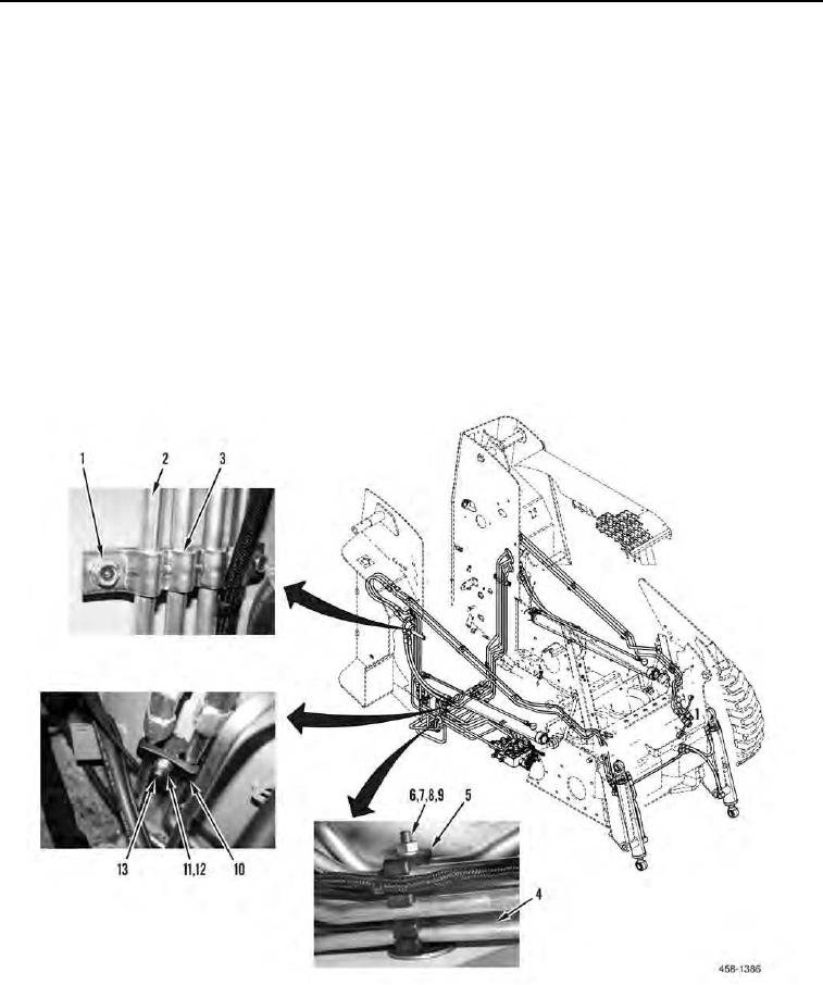
1. As required, remove two bolts (Figure 1, Item 1) and clamp (Figure 1, Item 3) from lines (Figure 1, Item 2).
2. As required, remove nut (Figure 1, Item 6), lockwasher (Figure 1, Item 7), lines (Figure 1, Item 4), clamp (Fig-
ure 1, Item 5), washer (Figure 1, Item 8), and bolt (Figure 1, Item 9) from machine. Discard lockwasher.
3. As required, remove locknut (Figure 1, Item 11), washer (Figure 1, Item 12), clamp (Figure 1, Item 10), and bolt
(Figure 1, Item 13) from machine. Discard locknut.
Figure 1. Clamps.
0082