
TM 5-3805-292-23
0081
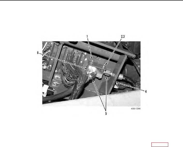
REMOVAL CONTINUED
3. Remove two hydraulic hoses (Figure 2, Item 5) from boom override valve (Figure 2, Item 6).
4. Remove two nuts (Figure 2, Item 2), bolts (Figure 2, Item 1), four washers (Figure 2, Item 3), and boom over-
ride valve (Figure 2, Item 6) from console bracket (Figure 2, Item 4).
Figure 2. Boom Override Valve.
0081
END OF TASK
CLEANING AND INSPECTION
00081
Clean, inspect, and flush hydraulic system IAW Mechanical General Maintenance Instructions (WP 0172).
END OF TASK
INSTALLATION
00081
1. Install boom override valve (Figure 2, Item 6), four washers (Figure 2, Item 3), two bolts (Figure 2, Item 1), and
nuts (Figure 2, Item 2) on console bracket (Figure 2, Item 4).
N OT E
Install hoses as tagged during removal.
2. Install two hydraulic hoses (Figure 2, Item 5) on boom override valve (Figure 2, Item 6).
3. Secure console bracket (Figure 1, Item 1) to machine with three washers (Figure 1, Item 2), bolts (Figure 1,
Item 3), and nut (Figure 1, Item 4).
END OF TASK