
TM 5-3805-292-23
0086
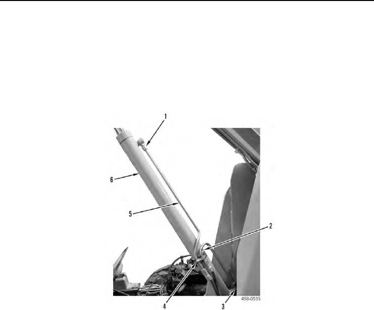
INSTALLATION CONTINUED
3. Install elbow (Figure 11, Item 3) on lift cylinder (Figure 11, Item 6).
N OT E
Install hydraulic hoses and lines as tagged during removal.
4. Install saddle insulator (Figure 11, Item 2) and loosely install two hydraulic lines (Figure 11, Item 5) on lift cylin-
der (Figure 11, Item 6) and connect four hydraulic line fittings (Figure 11, Item 1).
5. Install hose clamp (Figure 11, Item 4) on lift cylinder (Figure 11, Item 6) and tighten hydraulic lines.
Figure 11. Lift Cylinder Hoses and Lines.
0086