
TM 5-3805-292-23
0087
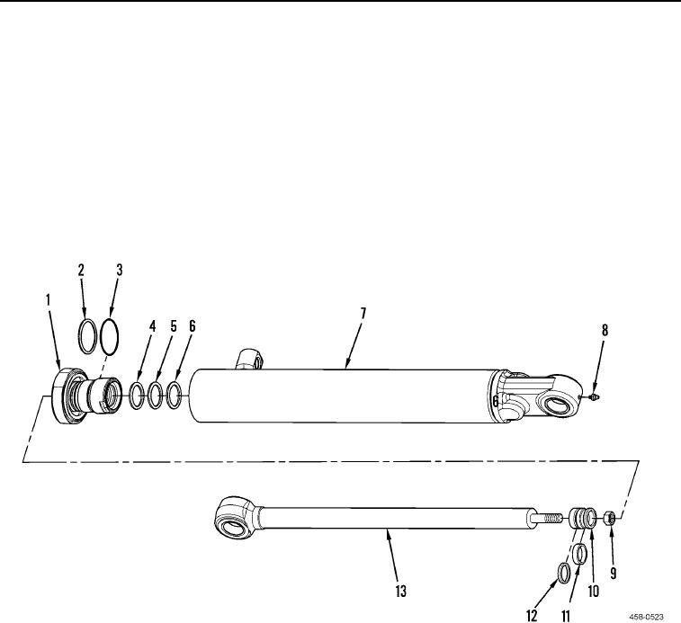
DISASSEMBLY
00087
1. Loosen cylinder head (Figure 2, Item 1) from tilt cylinder (Figure 2, Item 7) and pull piston rod (Figure 2, Item
13) straight out of tilt cylinder.
2. Place a padded support below piston rod (Figure 2, Item 13) near piston (Figure 2, Item 10) to prevent damage
to piston rod.
3. Remove nut (Figure 2, Item 9), piston (Figure 2, Item 10), and cylinder head (Figure 2, Item 1) from piston rod
(Figure 2, Item 13).
4. Remove and discard seal (Figure 2, Item 12) and wear ring (Figure 2, Item 11) from piston (Figure 2, Item 10).
5. Remove O-ring (Figure 2, Item 3), washer (Figure 2, Item 2), and seals (Figure 2, Items 4, 5, and 6) from cylin-
der head (Figure 2, Item 1). Discard seals and O-ring.
6. Remove fitting (Figure 2, Item 8) from tilt cylinder (Figure 2, Item 7).
Figure 2. Tilt Cylinder.
0087
END OF TASK