
TM 5-3805-292-23
0099
INSTALLATION CONTINUED
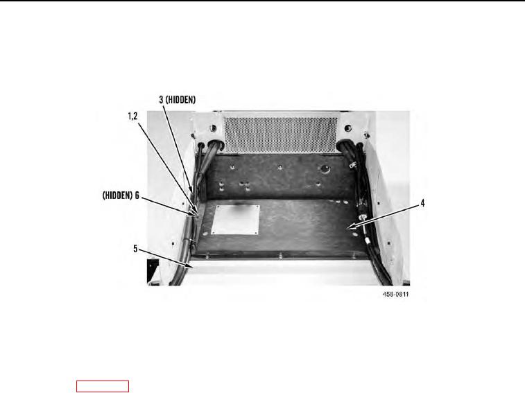
10. Position heat shield pad (Figure 10, Item 4) on plate (Figure 10, Item 5).
11. Install six bolts (Figure 10, Item 1), washers (Figure 10, Item 2), special washers (Figure 10, Item 6), and nuts
(Figure 10, Item 3) on machine.
Figure 10. Heat Shield Pad (Rear of ROPS).
0099
END OF TASK
FOLLOW-ON TASKS
00099
1. Close ROPS (WP 0134).
2. Install fire extinguisher (TM 5-3805-292-10).
3. Verify correct operation of machine (TM 5-3805-292-10).
END OF TASK
END OF WORK PACKAGE
0099-9/(10 blank)