
TM 5-3805-292-23
0106
INSTALLATION CONTINUED
2. Lower loader arm (Figure 17, Item 1) on machine and rest loader arms on jackstand (Figure 17, Item 2).
1
2
458-1064
Figure 17. Loader Arms Support.
0106
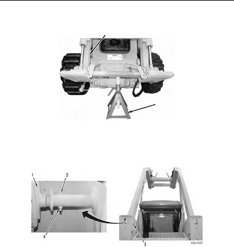
3. Install pin (Figure 18, Item 3), bolt (Figure 18, Item 2), and nut (Figure 18, Item 4) on loader arm (Figure 18,
Item 1).
4. Repeat step 3 to install second pin.
Figure 18. Loader Arm.
0106
5. Raise loader arms.