
TM 5-3805-292-23
0106
INSTALLATION CONTINUED
N OT E
Install hydraulic lines and hoses as noted during removal.
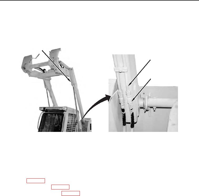
10. Install four hydraulic hoses (Figure 20, Item 3) on hydraulic lines (Figure 20, Item 2) on loader arm (Figure 20,
Item 1).
1
2
3
458-1068
Figure 20. Hydraulic Lines and Hoses.
0106
11. Lower loader arm (TM 5-3805-292-10)
END OF TASK
FOLLOW-ON TASKS
000106
1. Install step (WP 0118)
2. Install load capacity sign (WP 0119).
3. Install loader arm support strut (WP 0107).
4. Verify correct operation of machine (TM 5-3805-292-10).
END OF TASK
END OF WORK PACKAGE
0106-19/(20 blank)