
TM 5-3805-292-23
0106
INSTALLATION CONTINUED
WARN I N G
Use caution when handling heavy components. Provide adequate support and use
assistance. Failure to follow this warning may result in injury or death to personnel and
damage to equipment.
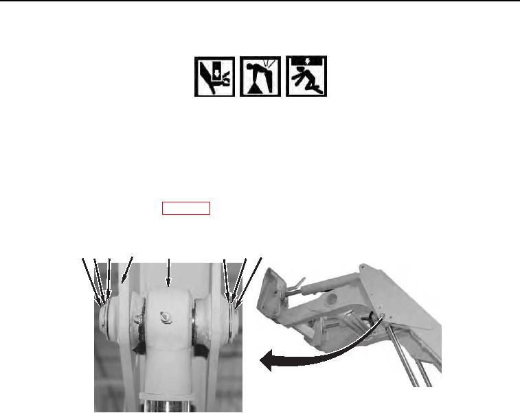
6. With assistance, install lift cylinder (Figure 19, Item 5), pin (Figure 19, Item 1), washers (Figure 19, Items 6 and
7), retaining ring (Figure 19, Item 8), washer (Figure 19, Item 3), and retaining ring (Figure 19, Item 2) on
loader arm (Figure 19, Item 4).
7. Repeat step 6 to install second lift cylinder.
8. Install loader arm support strut (WP 0107).
9. Remove lifting device from loader arm (Figure 19, Item 4).
12
4
5
7
3
8
6
458-1069
Figure 19. Lift Cylinder.
0106