
TM 5-3805-292-23
0127
INSTALLATION CONTINUED
000127
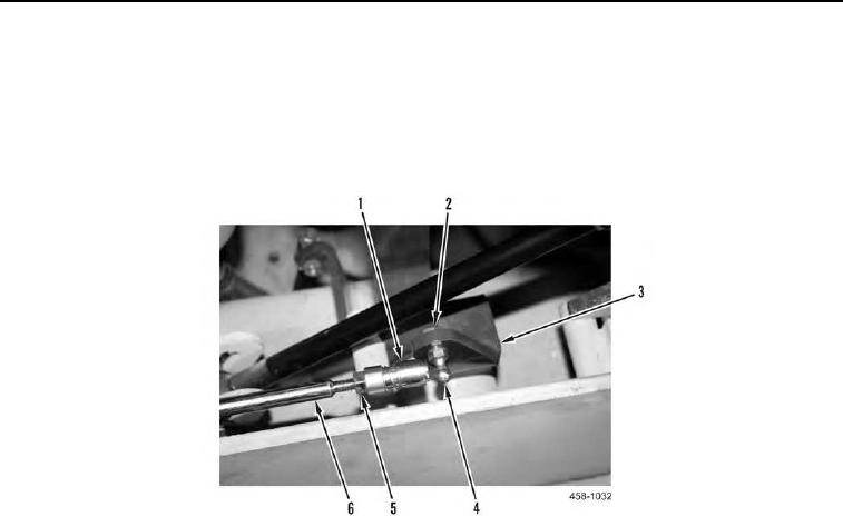
13. Install ball stud (Figure 13, Item 4) and nut (Figure 13, Item 2) on bracket (Figure 13, Item 3).
14. Install jam nut (Figure 13, Item 5) and sleeve (Figure 13, Item 1) on control rod (Figure 13, Item 6) and tighten
jam nut.
15. Position control rod and clamp on machine. Pull back sleeve (Figure 13, Item 1) and install control rod (Figure
13, Item 6) on ball stud (Figure 13, Item 4).
Figure 13. Actuator-to-Engine Control Rod (Front).
0127