
TM 5-3805-292-23
0127
INSTALLATION CONTINUED
N OT E
Tighten bolt hand tight.
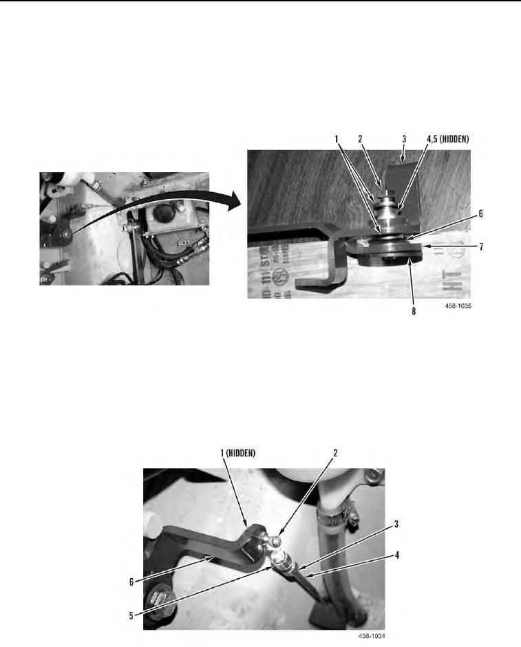
4. Install friction plate (Figure 9, Item 8), throttle lever (Figure 9, Item 7), spring washer (Figure 9, Item 6), two
spacers (Figure 9, Item 1), bushing (Figure 9, Item 4), bearing (Figure 9, Item 5), bracket (Figure 9, Item 3),
and bolt (Figure 9, Item 2) on machine.
Figure 9. Throttle Lever and Actuator Assembly.
0127
5. Install ball stud (Figure 10, Item 2) and nut (Figure 10, Item 1) on bracket (Figure 10, Item 6).
6. Install jam nut (Figure 10, Item 3) and sleeve (Figure 10, Item 5) on pedal linkage (Figure 10, Item 4) and
tighten jam nut (Figure 10, Item 3).
7. Pull sleeve back (Figure 10, Item 5) and install pedal linkage (Figure 10, Item 4) on ball stud (Figure 10,
Item 2).
Figure 10. Actuator-to-Pedal Linkage (Upper).
0127