
TM 5-3805-292-23
0127
INSTALLATION CONTINUED
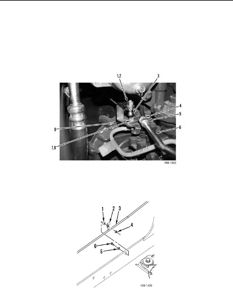
8. Position bracket (Figure 11, Item 9) on engine and install two new lockwashers (Figure 11, Item 8) and bolts
(Figure 11, Item 7) on bracket.
9. Install ball stud (Figure 11, Item 3), new lockwasher (Figure 11, Item 2), and nut (Figure 11, Item 1) on bracket
(Figure 11, Item 9).
10. Install jam nut (Figure 11, Item 5) and sleeve (Figure 11, Item 4) on control rod (Figure 11, Item 6) and tighten
jam nut.
11. Pull back on sleeve (Figure 11, Item 4) and install control rod (Figure 11, Item 6) on ball stud (Figure 11, Item
3).
Figure 11. Actuator-to-Engine Control Rod (Rear).
0127
12. Position clamp (Figure 12, Item 2) on control rod (Figure 12, Item 3) and install spacer (Figure 12, Item 1),
washer (Figure 12, Item 5), bolt (Figure 12, Item 6), and nut (Figure 12, Item 4) on machine.
Figure 12. Throttle Control Rod Retaining Clamp.
0127