
TM 5-3805-292-23
0127
REMOVAL CONTINUED
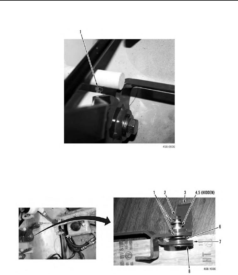
14. Loosen setscrew (Figure 5, Item 1).
Figure 5. Setscrew.
0127
15. Remove bolt (Figure 6, Item 2), two spacers (Figure 6, Item 1), bushing (Figure 6, Item 4), bearing (Figure 6,
Item 5), bracket (Figure 6, Item 3), spring washer (Figure 6, Item 6), throttle lever (Figure 6, Item 7), and friction
plate (Figure 6, Item 8) from machine.
Figure 6. Throttle Lever and Actuator Assembly.
0127