
TM 5-3805-292-23
0128
INSTALLATION CONTINUED
Wiper Arm and Motor Assembly - Continued
000128
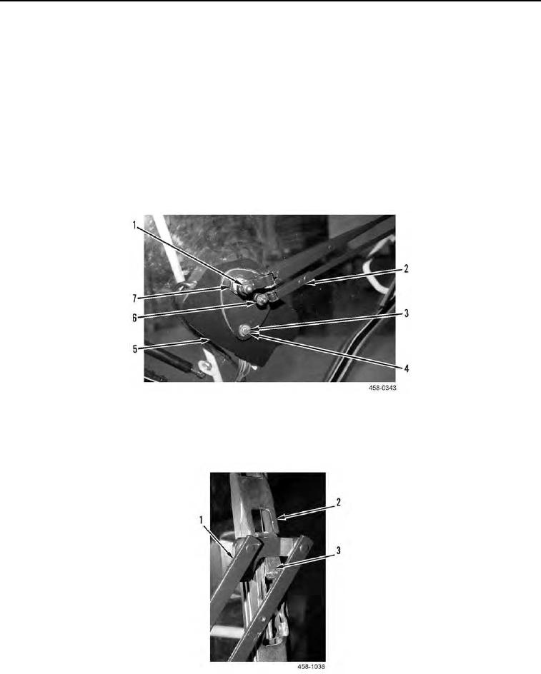
N OT E
Do not fully tighten jam nut so that screws and holes can be aligned.
4. Install jam nut (Figure 25, Item 7) on wiper motor assembly (Figure 25, Item 5).
5. Install two washers (Figure 25, Item 4) and bolts (Figure 25, Item 3) on wiper motor assembly (Figure 25, Item
5).
6. Fully tighten jam nut (Figure 25, Item 7) and two screws (Figure 25, Item 3).
7. Install wiper arm (Figure 25, Item 2) on wiper motor assembly (Figure 25, Item 5).
8. Install washer (Figure 25, Item 6) and two nuts (Figure 25, Item 1) on wiper motor assembly (Figure 25,
Item 5).
Figure 25. Wiper Arm.
0128
9. Install wiper blade (Figure 26, Item 2) on wiper arm (Figure 26, Item 1) and press clip (Figure 26, Item 3).
.
Figure 26. Wiper Blade.
0128