
TM 5-3805-292-23
0128
INSTALLATION CONTINUED
Door Handle and Latch Assembly - Continued
000128
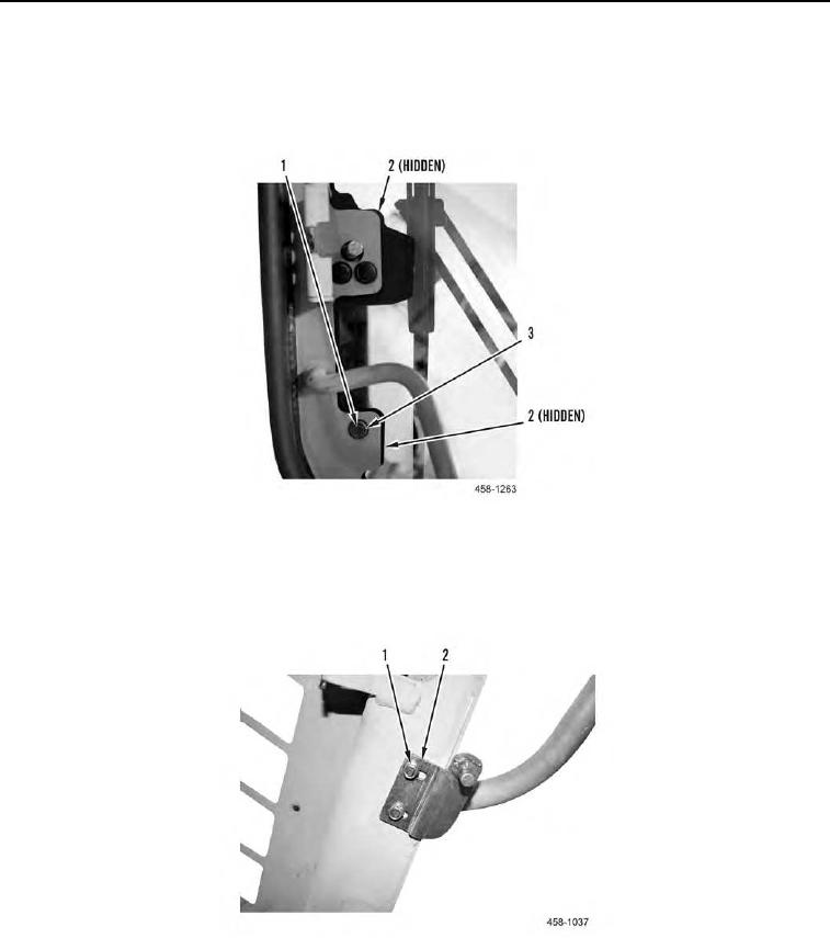
3. Install two gaskets (Figure 19, Item 2), three washers (Figure 19, Item 3) and bolts (Figure 19, Item 1) on front
door interior.
Figure 19. Door Handle (Interior).
0128
4. Align friction catch stud (Figure 20, Item 2) to marked location.
5. Install friction catch stud (Figure 20, item 2) and two bolts (Figure 20, Item 1) on door frame.
Figure 20. Friction Catch Stud.
0128