
TM 5-3805-292-23
0128
INSTALLATION CONTINUED
Door Handle and Latch Assembly - Continued
000128
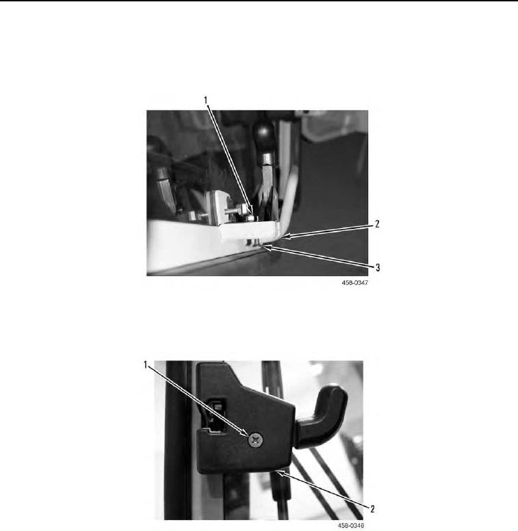
6. Position right thumb rotary latch (Figure 21, Item 2) on front door interior and install two screws (Figure 21,
Item 3) and nuts (Figure 21, Item 1) on right thumb rotary latch.
Figure 21. Right Thumb Rotary Latch.
0128
7. Position latch cover (Figure 22, Item 2) on front door interior and install screw (Figure 22, Item 1).
Figure 22. Latch Cover.
0128
8. Open and close front door several times to ensure correct operation of front door (TM 5-3805-292-10).
END OF TASK