
TM 5-3805-292-23
0128
INSTALLATION CONTINUED
Wiper Arm and Motor Assembly
000128
1. Assemble mounting bracket (Figure 23, Item 5), two spacers (Figure 23, Item 2), bushing (Figure 23, Item 3),
new seal (Figure 23, Item 4), wiper motor (Figure 23, Item 7), and case (Figure 23, Item 6) and position assem-
bly on front door interior.
Figure 23. Wiper Motor and Bracket.
0128
2. Connect electrical connector (Figure 23, Item 1) to bracket (Figure 23, Item 4).
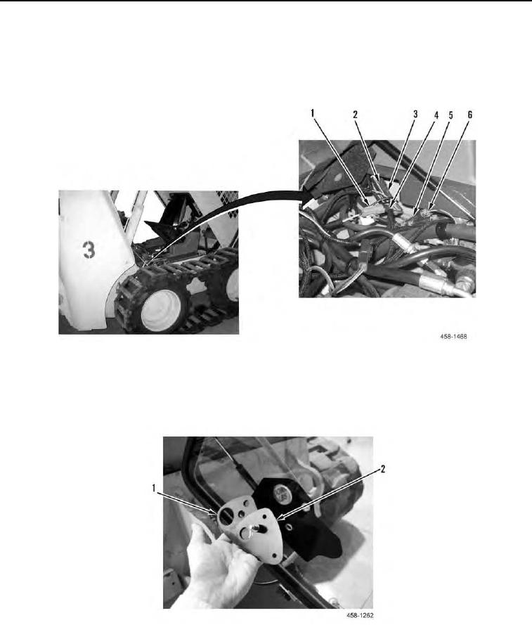
3. Position new seal (Figure 24, Item 1) and wiper arm mounting plate (Figure 24, Item 2) on front door exterior.
Figure 24. Wiper Arm Mounting Plate.
0128