TM 5-3805-292-23
0130
INSTALLATION CONTINUED
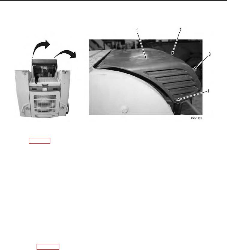
6. Install two end cap covers (Figure 15, Item 3) and eight screws (Figure 15, Item 1) on case (Figure 15, Item 2).
Figure 15. End Cap Covers and Retaining Hardware.
0130
7. Tilt ROPS (WP 0134).
8. Install two upper heater hoses (Figure 16, Item 2) and wiring harness (Figure 16, Item 9) through hole (Figure
16, Item 1) in body panel.
9. Install tubing (Figure 16, Item 4) and two hose clamps (Figure 16, Item 3) on upper heater hoses (Figure 16,
Item 2).
N OT E
Remove all caps from hoses and install all hoses as noted in removal.
10.
Connect two upper heater hoses (Figure 16, Item 2) on lower heater hoses (Figure 16, Item 6).
11.
Install two hose clamps (Figure 16, Item 5) on lower heater hoses (Figure 16, Item 6).
N OT E
Install wiring harness as noted during removal.
12.
Connect wiring harness (Figure 16, Item 9).
13.
Install new tiedown strap (Figure 16, Item 7) on lower heater hoses (Figure 16, Item 6), drain hose (Figure 16,
Item 8) and wiring harness (Figure 16, Item 9).
14.
Close ROPS (WP 0134).

