
TM 5-3805-292-23
0131
REMOVAL CONTINUED
N OT E
Handle contains caps over the screwholes which must be pried open.
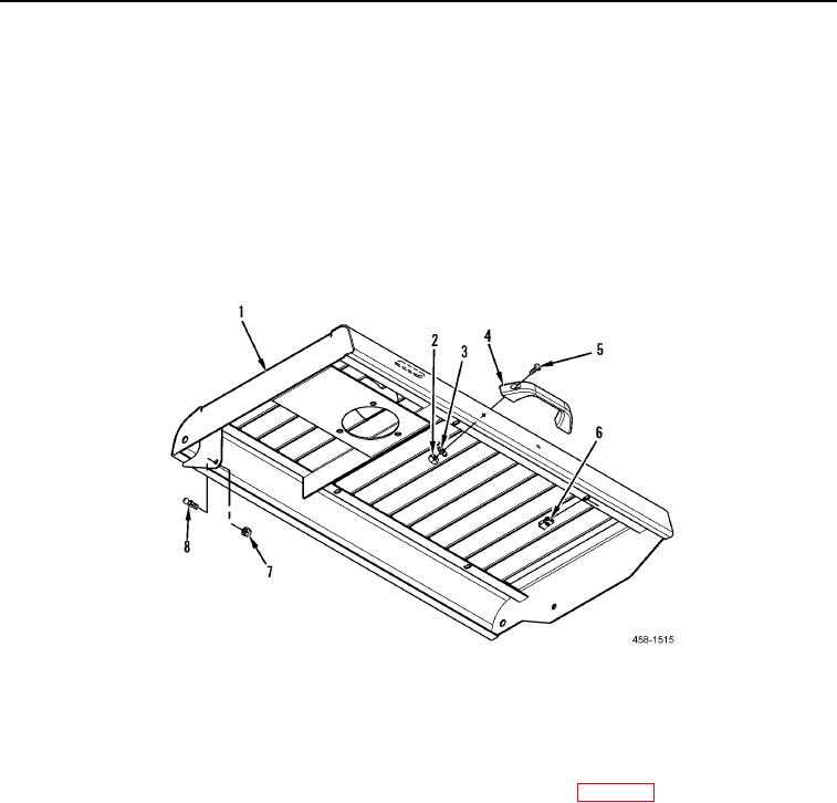
9. Remove two pan head screws (Figure 2, Item 5), lockwashers (Figure 2, Item 3), and locknuts (Figure 2, Item
2) from handle (Figure 2, Item 4). Discard lockwashers and locknuts.
10. Remove handle (Figure 2, Item 4) from engine compartment hood (Figure 2, Item 1).
11. Remove four U-nuts (Figure 2, Item 6) from engine compartment hood (Figure 2, Item 1).
12. Remove ball stud (Figure 2, Item 8) and locknut (Figure 2, Item 7) from engine compartment hood (Figure 2,
Item 1). Discard locknut.
Figure 2. Engine Compartment Hood Hardware.
0131
END OF TASK
CLEANING AND INSPECTION
000131
Clean and inspect all parts IAW Mechanical General Maintenance Instructions (WP 0172).
END OF TASK
INSTALLATION
000131
1. Install ball stud (Figure 2, Item 8) and new locknut (Figure 2, Item 7) on engine compartment hood (Figure 2,
Item 1).
2. Install four U-nuts (Figure 2, Item 6) on engine compartment hood (Figure 2, Item 1).
3. Install handle (Figure 2, Item 4) on engine compartment hood (Figure 2, Item 1).
4. Install two pan head screws (Figure 2, Item 5), new lockwashers (Figure 2, Item 3), and new locknuts (Figure 2,
Item 2), on handle (Figure 2, Item 4).