
TM 5-3805-292-23
0145
REMOVAL CONTINUED
4. Remove two bolts (Figure 3, Item 1) and washers (Figure 3, Item 2) from LH side of machine.
5. Remove access cover (Figure 3, Item 3) from interior LH side of machine.
Figure 3. Access Cover.
0145
N OT E
Tag all electrical connections to aid in installation.
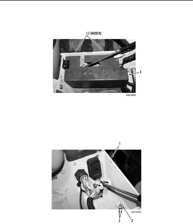
6. Remove bolt (Figure 4, Item 2) and two ground wires (Figure 4, Item 3) from ROPS assembly (Figure 4, Item
1).
Figure 4. Ground Wires.
0145