
TM 5-3805-292-23
0146
REMOVAL CONTINUED
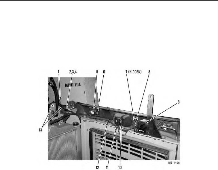
5. Remove bolt (Figure 3, Item 2), washer (Figure 3, Item 3), and clamp (Figure 3, Item 4) from machine.
6. Disconnect four harness connectors (Figure 3, Item 6) from two tail lights (Figure 3, Item 5).
7. Disconnect harness connector (Figure 3, Item 11) from backup light (Figure 3, Item 10).
8. Remove two locknuts (Figure 3, Item 7), and wires (Figure 3, Item 8) from backup alarm (Figure 3, Item 9). Dis-
card locknuts.
9. Remove chassis harness (Figure 3, Item 13) from clamp (Figure 3, Item 12).
10. Pull fuel sending wiring harness (Figure 3, Item 13) through opening (Figure 3, Item 1).
Figure 3. Rear Door Chassis Wiring.
0146