
TM 5-3805-292-23
0146
REMOVAL CONTINUED
N OT E
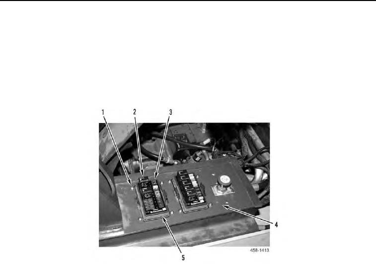
Note location of fuses and relays for installation.
18. Remove fuses (Figure 7, Item 3) and relays (Figure 7, Item 2) from two fuse panels (Figure 7, Item 5). Refer to
TM 5-3805-292-10.
19. Remove eight screws (Figure 7, Item 1) and two fuse panels (Figure 7, Item 5) from left joystick support (Fig-
ure 7, Item 4).
Figure 7. Fuse Panel.
0146