• Home
  • Download PDF
  • Order CD-ROM
  • Order in Print
Figure 3. Rear Door Chassis Wiring.
Figure 6. Hydraulic Pump Wiring.

Field Maintenance Manual For M400T And M400W
Page Navigation
  972    973    974    975    976  977  978    979    980    981    982  
img
.
TM 5-3805-292-23
0146
REMOVAL CONTINUED
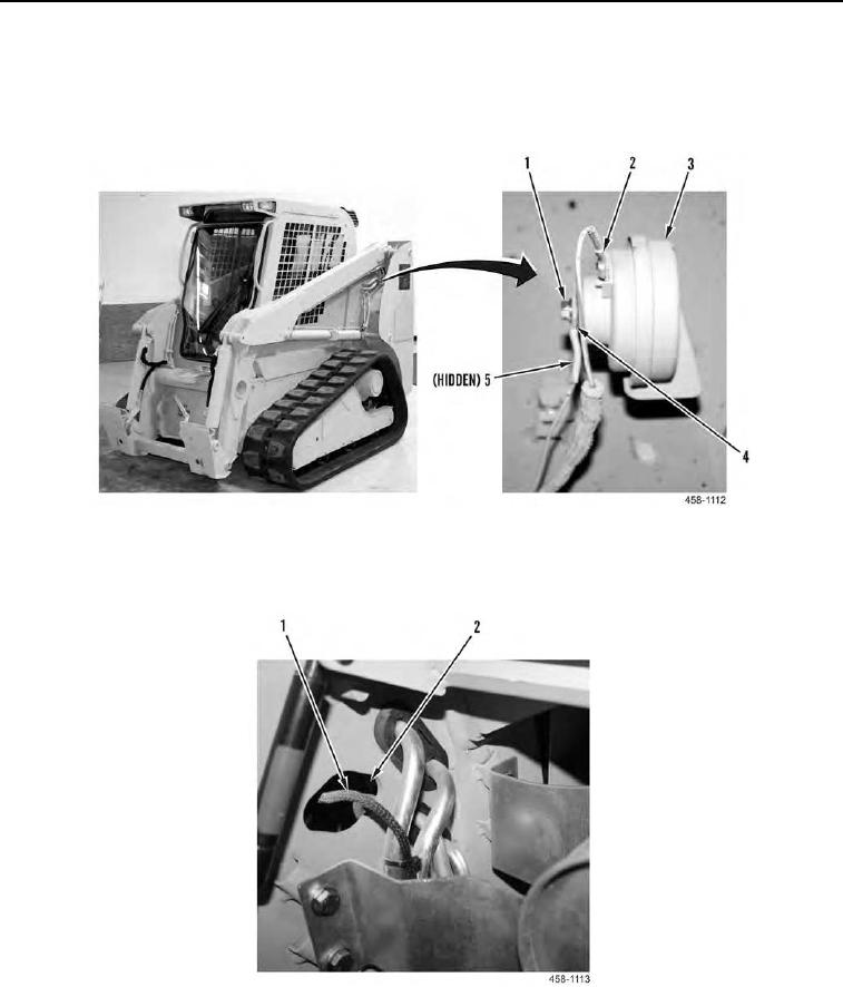
11. Remove nut (Figure 4, Item 1), wire eyelet (Figure 4, Item 4), and horn (Figure 4, Item 3) from bracket (Figure
4, item 5).
12. Remove wire connector (Figure 4, Item 2) from horn (Figure 4, Item 3).
Figure 4. Horn Wiring.
0146
13. Pull horn wiring (Figure 5, Item 1) through opening (Figure 5, item 2).
Figure 5. Horn Wiring.
0146
0146-5


Privacy Statement
Press Release
Contact

© Copyright Integrated Publishing, Inc.. All Rights Reserved.