
TM 5-3805-292-23
0146
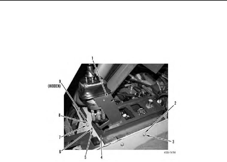
REMOVAL CONTINUED
20. Remove two bolts (Figure 8, Item 3) and washers (Figure 8, Item 2) from machine.
21. Remove bolt (Figure 8, Item 7), washer (Figure 8, Item 8) and nut (Figure 8, Item 9) from left hand joystick sup-
port (Figure 8, Item 1).
22. Remove bolt (figure 9, item 6), washer (figure 9, item 5), and plate (figure 9, item 4) from machine.
23. Position left hand joystick support (Figure 8, Item 1) aside.
Figure 8. Left Joystick Support.
0146