
TM 5-3805-292-23
0152
REMOVAL CONTINUED
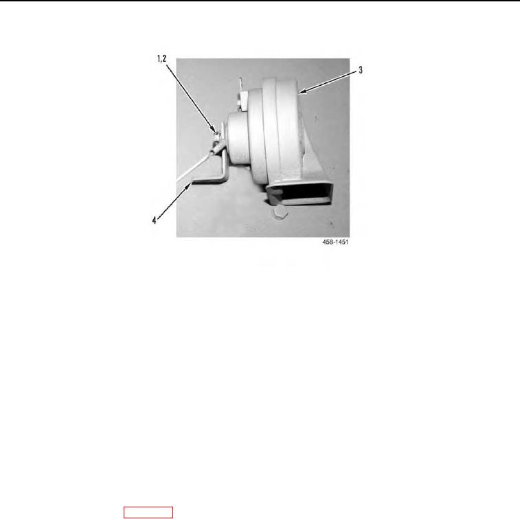
Figure 2. Horn.
0152
END OF TASK
INSTALLATION
000152
N OT E
Install wires and electrical connectors as tagged during removal
1. Install horn (Figure 1, Item 2), nut (Figure 1, Item 6), bracket (Figure 1, Item 3), washer (Figure 1, Item 5), and
bolt (Figure 1, Item 4) on machine.
2. Install bracket (Figure 2, Item 4), wire (Figure 2, Item 2), and nut (Figure 2, Item 1) on horn (Figure 2, Item 3).
3. Connect wire (Figure 1, Item 1) to horn (Figure 1, Item 2).
END OF TASK
FOLLOW-ON TASKS
000152
1. Connect battery power (WP 0142).
2. Verify correct operation of machine (TM 5-3805-292-10).
END OF TASK
END OF WORK PACKAGE
0152-3/(4 blank)