
TM 5-3805-292-23
0152
REMOVAL
000152
N OT E
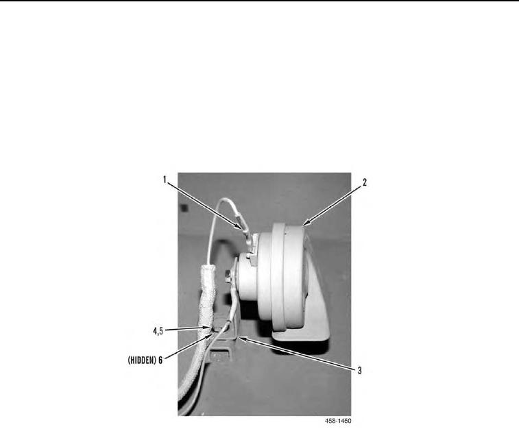
Tag wires and electrical connectors to aid in installation.
1. Remove wire (Figure 1, Item 1) from horn (Figure 1, Item 2).
2. Remove bolt (Figure 1, Item 4), washer (Figure 1, Item 5), nut (Figure 1, Item 6), bracket (Figure 1, Item 3), and
horn (Figure 1, Item 2) from machine.
3. Remove nut (Figure 2, Item 1), wire (Figure 2, Item 2), and bracket (Figure 2, Item 4) from horn (Figure 2,
Item 3).
Figure 1. Horn.
0152