
TM 5-3805-292-23
0159
REMOVAL CONTINUED
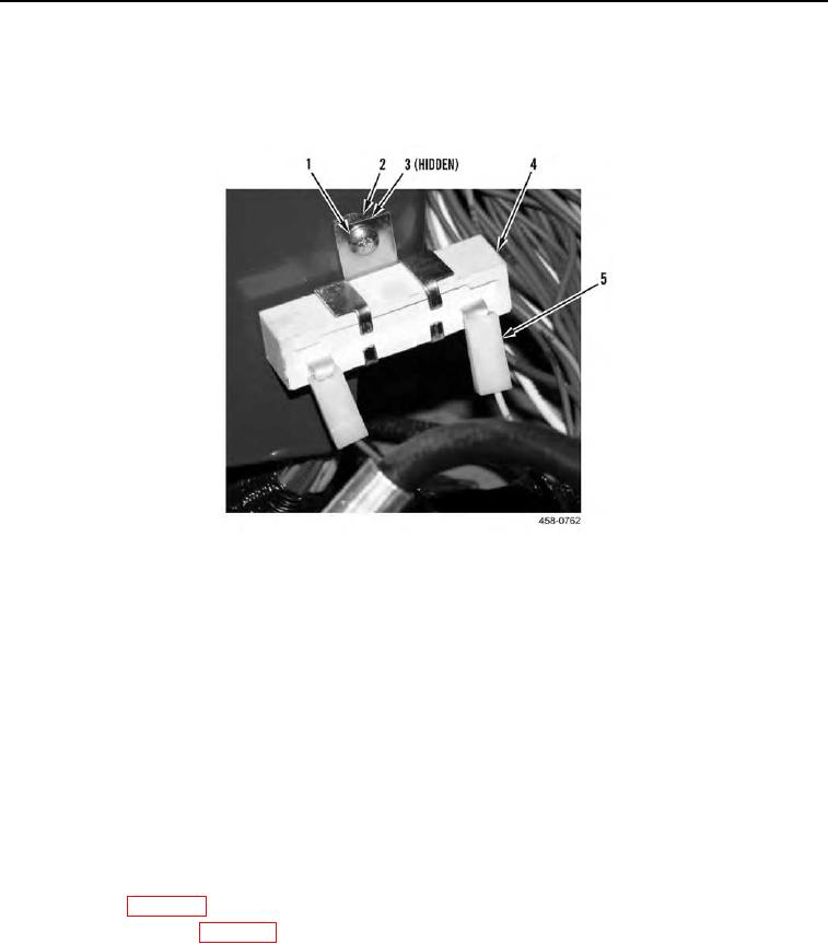
1. Disconnect two wires (Figure 1, Item 5) from resistor (Figure 1, Item 4).
2. Remove screw (Figure 1, Item 1), nut (Figure 1, Item 2), washer (Figure 1, Item 3), and resistor (Figure 1, Item
4) from engine compartment.
Figure 1. Engine Compartment.
0159
END OF TASK
INSTALLATION
000159
1. Install resistor (Figure 1, Item 4), screw (Figure 1, Item 1), washer (Figure 1, Item 3), and nut (Figure 1, Item 2)
in engine compartment.
N OT E
Install wires as tagged during removal.
2. Connect two wires (Figure 1, Item 5) to resistor (Figure 1, Item 4).
END OF TASK
FOLLOW-ON TASKS
000159
1. Lower ROPS (WP 0134).
2. Connect battery power (WP 0142).
3. Verify correct operation of machine (TM 5-3805-292-10).
END OF TASK
END OF WORK PACKAGE