
TM 5-3805-292-23
0169
DISASSEMBLY
000169
Hoses
000169
N OT E
Tag hoses to aid in installation.
Cap lines, fittings, and hoses.
1. Position hammer on level ground and remove hammer from machine (TM 5-3805-292-10).
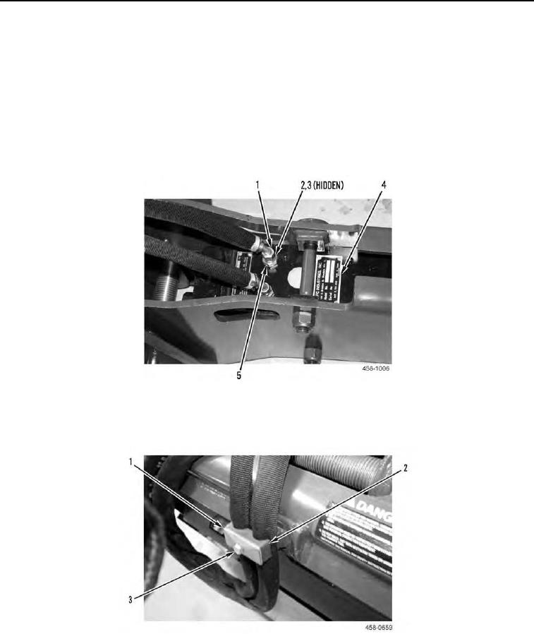
2. Disconnect two hydraulic hoses (Figure 1, Item 1), fittings (Figure 1, Item 5), washers (Figure 1, Item 2) and
O-rings (Figure 1, Item 3) from hammer (Figure 1, Item 4). Discard O-rings.
Figure 1. Hoses and Fittings.
0169
3. Remove bolt (Figure 2, Item 3), plate (Figure 2, Item 1), and hose cushion (Figure 2, Item 2) from assembly.
Figure 2. Hose Cushion.
0169