
TM 5-3805-292-23
0169
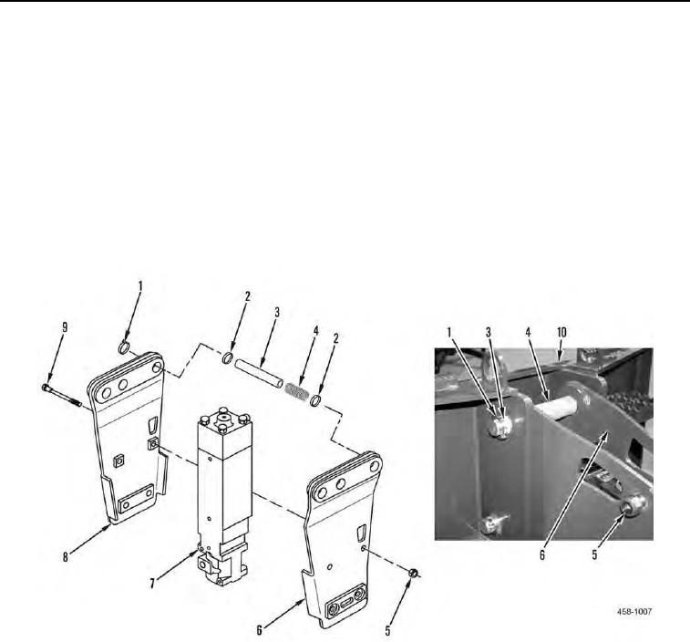
DISASSEMBLY CONTINUED
Hammer
000169
8. Remove four retaining clips (Figure 4, Item 1), two springs (Figure 4, Item 4), pins (Figure 4, Item 3), and four
bushings (Figure 4, Item 2) from brackets (Figure 4, Items 6 and 8).
9. Use lifting device to separate hammer (Figure 4, Item 7) and brackets (Figure 4, Items 6 and 8) from frame
(Figure 4, Item 10) and lay hammer and bracket assembly on side with nuts (Figure 4, Item 5) facing up.
10. Remove four nuts (Figure 4, Item 5) and bolts (Figure 4, Item 9) from two brackets (Figure 4, Items 6 and 8).
N OT E
Nut-side bracket is different from bolt-side bracket.
11. With assistance, remove nut-side bracket (Figure 4, Item 6) from hammer (Figure 4, Item 7).
Figure 4. Hammer Assembly.
0169
12. Use lifting device to lift hammer (Figure 4, Item 7) from bolt-side bracket (Figure 4, Item 8).
13. Support hammer on blocks of wood.
END OF TASK
0169-4