
TM 5-3805-292-23
0169
ASSEMBLY CONTINUED
Gas Valve Assembly
000169
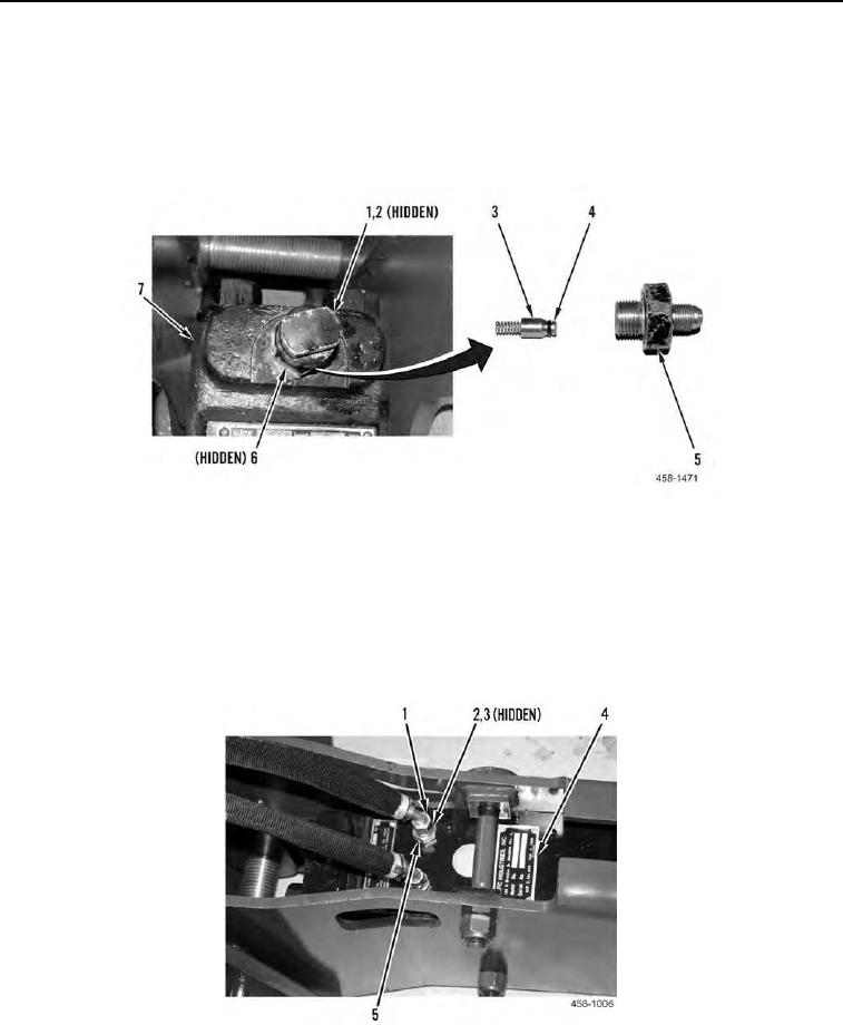
1. Position spring (Figure 8, Item 3) and new O-ring (Figure 8, Item 4) on hammer (Figure 8, Item 7).
2. Install new O-ring (Figure 8, Item 6) and fitting (Figure 8, Item 5) on hammer (Figure 8, Item 7).
3. Install new O-ring (Figure 8, Item 2) and cap (Figure 8, Item 1) on fitting (Figure 8, Item 5).
Figure 8. Gas Valve Assembly.
0169
4. Charge hammer with nitrogen. Refer to Nitrogen Charging/Discharging in this work package.
5. Install two new O-rings (Figure 9, Item 3), washers (Figure 9, Item 2), and fittings (Figure 9, Item 5) on hammer
(Figure 9, Item 4).
Hose
000169
1. Connect two hydraulic hoses (Figure 9, Item 1) to fittings (Figure 9, Item 5).
Figure 9. Hoses and Fittings.
0169
0169-7