
TM 5-3805-292-23
0169
ASSEMBLY CONTINUED
Hammer - Continued
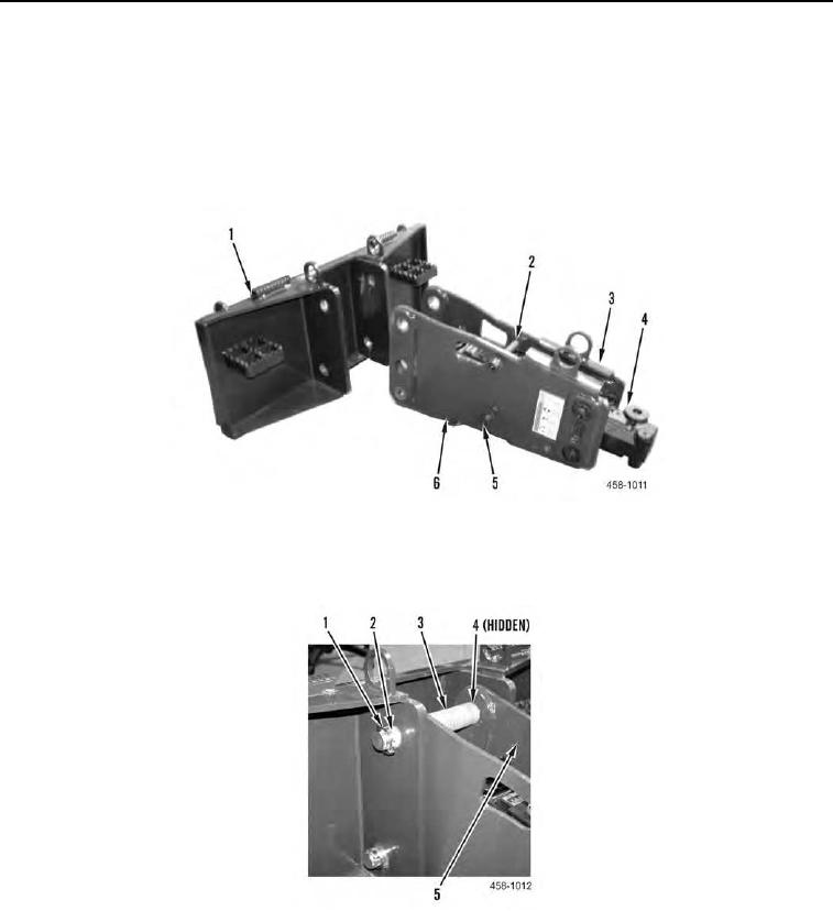
3. With assistance, position nut-side bracket (Figure 7, Item 6) on hammer (Figure 7, Item 4).
4. Install four nuts (Figure 7, Item 5) on bolts (Figure 7, Item 2) and tighten to 225 to 295 lb-ft (305 to 400 Nm).
5. Use lifting device to align hammer (Figure 7, Item 4) and two brackets (Figure 7, Items 3 and 6) with frame
(Figure 7, Item 1).
Figure 6. Hammer and Frame.
0169
6. Install two springs (Figure 7, Item 3), pins (Figure 7, Item 2), four bushings (Figure 7, Item 4), and retaining
clips (Figure 7, Item 1) on two brackets (Figure 7, Item 5).
Figure 7. Spring and Pin.
0169
0169-6