
TM 5-3805-292-23
0171
DISASSEMBLY CONTINUED
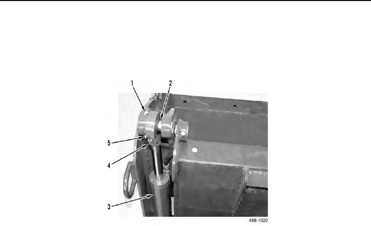
9. Remove grease fitting (Figure 3, Item 4) from cylinder (Figure 3, Item 3).
10. Remove capscrew (Figure 3, Item 1) and locknut (Figure 3, Item 5) from upper cylinder pin (Figure 3, Item 2).
Discard locknut.
11. Drive upper cylinder pin (Figure 3, Item 2) from assembly.
Figure 3. Upper Cylinder.
0171
12. Pull cylinder (Figure 4, Item 1) back and disconnect two hoses (Figure 4, Item 2) from cylinder.
13. Repeat steps 9 through 12 for other side.
N OT E
Hose assemblies with tees can only be removed through opening on either side of bucket
near cylinder. Do not attempt to remove hose assemblies through opening at top of
bucket.
14. Remove hose assemblies with tees (Figure 4, Item 2) from assembly.