
TM 5-3805-298-23-2
0165
CHARGING SYSTEM TEST CONTINUED
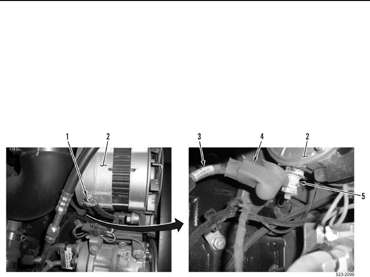
7. Position cover (Figure 3, Item 4) on positive alternator cable (Figure 3, Item 3) to access B+ terminal
(Figure 3, Item 5).
8. Place multimeter positive lead on B+ terminal (Figure 3, Item 5) of alternator (Figure 3, Item 2).
9. Place multimeter negative lead on negative terminal (Figure 3, Item 1) of alternator (Figure 3, Item 2).
10. With engine still running, monitor digital multimeter. Voltage reading should be 24-28 volts.
a. If voltage is within specified range, alternator and charging system are OK. Turn ignition switch and battery
disconnect switch to OFF position (TM 5-3805-298-10). Install cover (Figure 3, Item 4) on B+ terminal
(Figure 3, Item 5).
b. If voltage is less than 24 volts or more than 28 volts, then the alternator is faulty.
Figure 3. Alternator Terminals.
0165
END OF TASK
END OF WORK PACKAGE