
TM 5-3805-298-23-2
0175
COUNTERWEIGHT REMOVAL TOOL ASSEMBLY
000175
NOTE
All components of counterweight removal tool are located in BII tool bag.
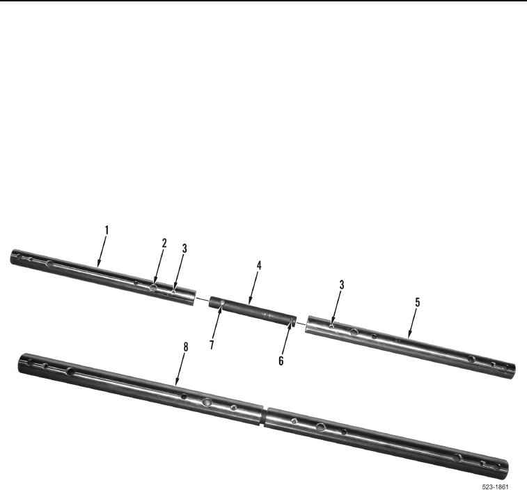
1. Position tube (Figure 2, Item 1) and tube (Figure 2, Item 5) so that tube ends with small holes
(Figure 2, Item 3) are positioned adjacent to each other.
2. Install adapter (Figure 2, Item 4) into end of tube (Figure 2, Item 5) so that small spring loaded pin (Figure 2,
Item 6) locks into first small hole (Figure 2, Item 3) in tube (Figure 2, Item 5).
3. Install other end of adapter (Figure 2, Item 4) into tube (Figure 2, Item 1) so that large spring loaded pin
(Figure 2, Item 7) locks into first large hole (Figure 2, Item 2) in tube (Figure 2, Item 1).
4. Set half completed tool (Figure 2, Item 8) aside.
5. Repeat steps 1 through 4 for remaining two tubes and one adapter.
Figure 2. Half Counterweight Removal Tool.
0175