TM 5-3805-298-23-2
0175
COUNTERWEIGHT REMOVAL TOOL ASSEMBLY CONTINUED
NOTE
Do not install second pin at this time.
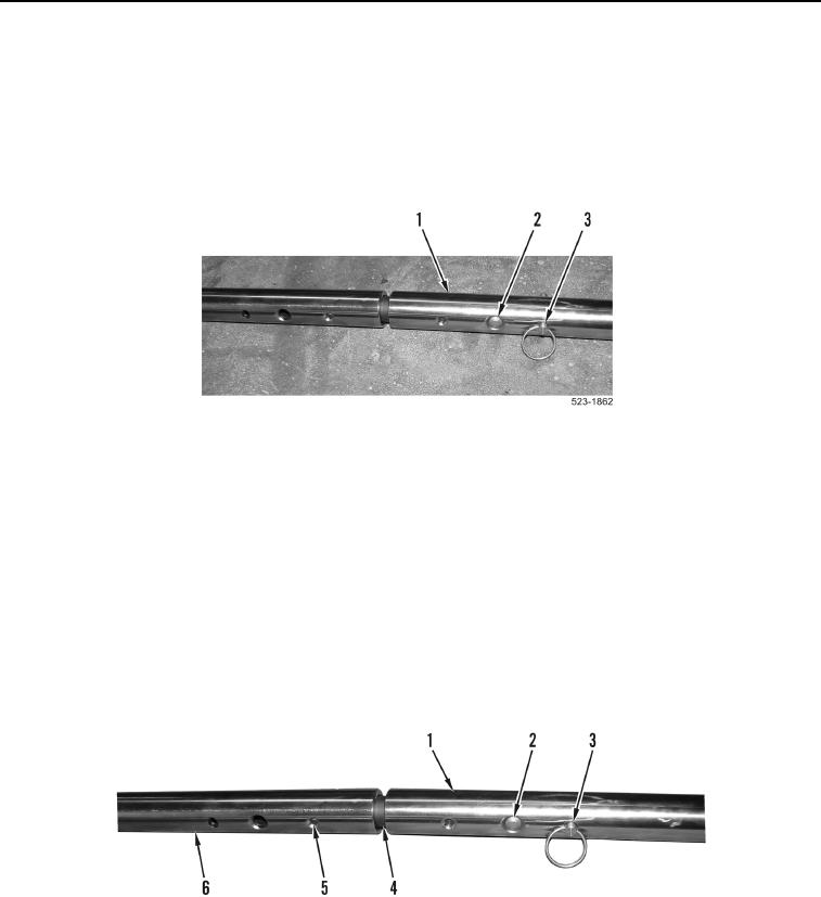
9. Install pin (Figure 5, Item 3) through tube (Figure 5, Item 1) on same end of tool that bracket link was installed,
in hole next to large spring loaded pin (Figure 5, Item 2).
Figure 5. Counterweight Removal Tool Pin.
0175
END OF TASK
COUNTERWEIGHT REMOVAL TOOL DISASSEMBLY
000175
1. Remove pin (Figure 6, Item 3) from tube (Figure 6, Item 1).
2. Depress large spring loaded pin (Figure 6, Item 2) and remove tube (Figure 6, Item 1) from adapter
(Figure 6, Item 4).
3. Depress small spring loaded pin (Figure 6, Item 5) and remove adapter (Figure 6, Item 4) from tube
(Figure 6, Item 6).
4. Repeat steps 2 and 3 from remaining tubes and adapters.
5. Stow all counterweight removal tool components in BII tool bag.
Figure 6. Counterweight Removal Tool Pin.
0175
END OF TASK

