
TM 5-3805-298-23-2
0175
COUNTERWEIGHT REMOVAL TOOL ASSEMBLY CONTINUED
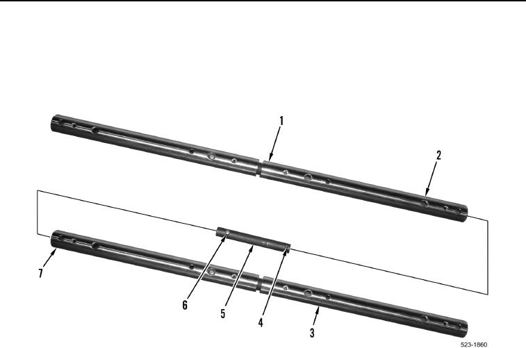
6. Install remaining adapter (Figure 3, Item 5) into one end of half completed tool (Figure 3, Item 3) so that small
spring loaded pin (Figure 3, Item 4) locks into second hole (Figure 3, Item 7) in tool (Figure 3, Item 3).
7. Install other end of adapter (Figure 3, Item 5) into one end of half completed tool (Figure 3, Item 1) so that large
spring loaded pin (Figure 3, Item 6) locks into third hole (Figure 3, Item 2) in tool (Figure 3, Item 1).
Figure 3. Counterweight Removal Tool Adapter.
0175