
TM 5-3805-298-23-2
0175
COUNTERWEIGHT INSTALLATION CONTINUED
1. Attach nylon sling to one counterweight (Figure 11, Item 3) and suitable lifting device.
WARNING
Use extreme caution when loosening or installing counterweight to ensure fingers are not
caught between counterweight and machine or bucket mounting bracket during removal,
alignment or installation to prevent injury to personnel.
NOTE
Step 2 applies to counterweight mounted to MP Bucket only. If installing counterweight
secured to pallet, skip to step 3.
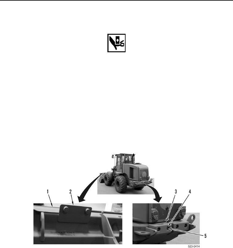
2. Remove two bolts (Figure 11, Item 4) and counterweight (Figure 11, Item 3) from mounting bracket
(Figure 11, Item 2) on MP bucket (Figure 11, Item 1).
3. Install counterweight (Figure 11, Item 3), two washers (Figure 11, Item 5) and bolts (Figure 11, Item 4) to rear of
machine.
4. Repeat steps, as appropriate to install second counterweight (Figure 11, Item 3) to rear of machine.
5. Remove nylon sling from lifting device.
Figure 11. Rear Counterweights.
0175
END OF TASK
END OF WORK PACKAGE
0175-25/(26 blank)