
TM 5-3805-298-23-2
0177
INSTALLATION CONTINUED
CAUTION
Remove all caps from hydraulic openings and component connections during installation.
Failure to follow this caution may result in damage to equipment.
NOTE
Install hoses and tubes as noted during removal.
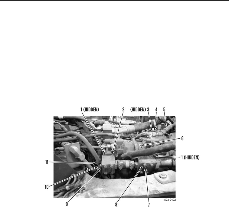
99. Install new O-ring (Figure 111, Item 3), hose (Figure 111, Item 5) and tighten tube nut (Figure 111, Item 4) on
implement pump (Figure 111, Item 6).
100. With assistance, install two new O-rings (Figure 111, Item 1), manifold assembly (Figure 111, Item 2), eight
washers (Figure 111, Item 8) and bolts (Figure 111, Item 7) on machine.
101. Install ladder clip (Figure 111, Item 11), washer (Figure 111, Item 9) and bolt (Figure 111, Item 10) on manifold
assembly (Figure 111, Item 2).
Figure 111. Manifold Assembly.
0177