
TM 5-3805-298-23-2
0177
INSTALLATION CONTINUED
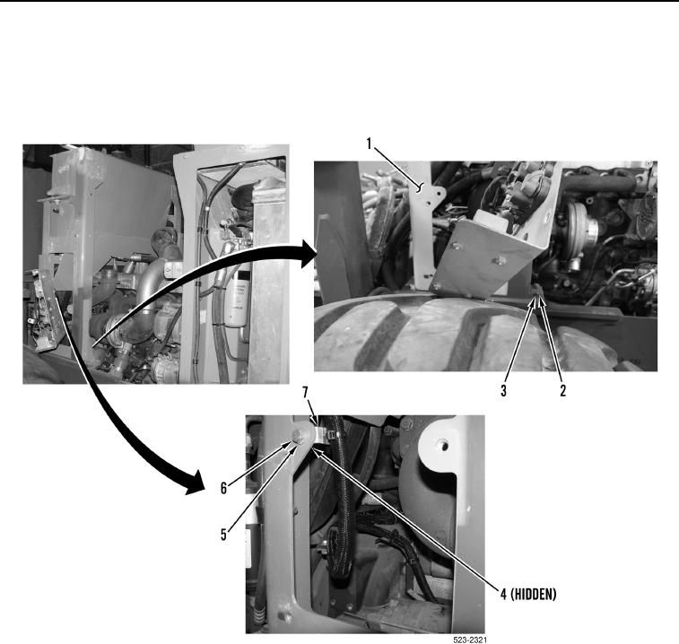
102. With assistance, install left hydraulic tank support bracket (Figure 112, Item 1), four washers (Figure 112,
Item 2) and bolts (Figure 112, Item 3) on machine.
103. Install bolt (Figure 5, Item 6), two washers (Figure 5, Item 5), ladder clip (Figure 5, Item 7) and nut (Figure 5,
Item 4)on left hydraulic tank support bracket (Figure 5, Item 1).
Figure 112. Left Hydraulic Tank Support Bracket.
0177