
TM 5-3805-298-23-2
0180
REMOVAL CONTINUED
WARNING
Engine coolant is very slippery. Immediately wipe up any spills. Failure to follow this
warning may result in injury to personnel.
NOTE
Tag and mark hose to aid installation.
Plug or cap hose end and open port.
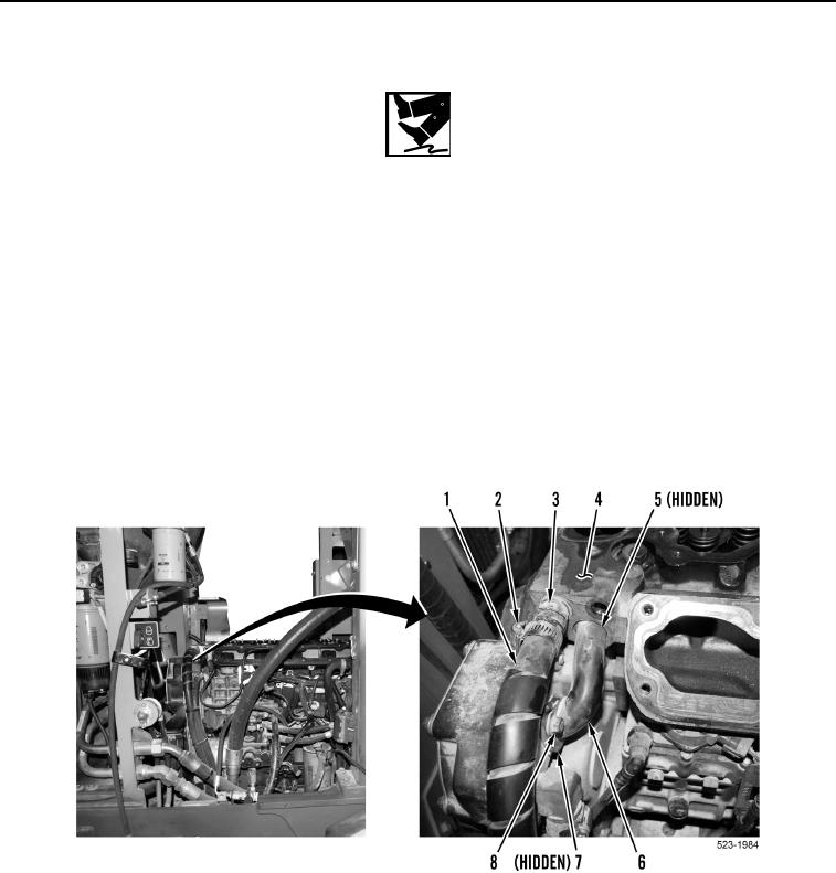
10. Loosen clamp (Figure 4, Item 2) and remove hose (Figure 4, Item 1) from hose connector (Figure 4, Item 3).
11. Remove hose connector (Figure 4, Item 3) from cylinder head (Figure 4, Item 4).
12. Remove two bolts (Figure 4, Item 8) from bypass tube (Figure 4, Item 6).
13. Remove bypass tube (Figure 4, Item 6) and two O-rings (Figure 4, Items 5 and 7) from cylinder head
(Figure 4, Item 4). Discard O-rings.
Figure 4. Heater Hose and Bypass Tube.
0180