
TM 5-3805-298-23-2
0187
VALVE COVER BASE REMOVAL
000187
1. Remove valve cover (see procedure in this work package).
2. Remove primary fuel lines (WP 0210).
NOTE
Tag wires and wiring harnesses to aid installation.
Note routing of wires and wiring harnesses to aid installation.
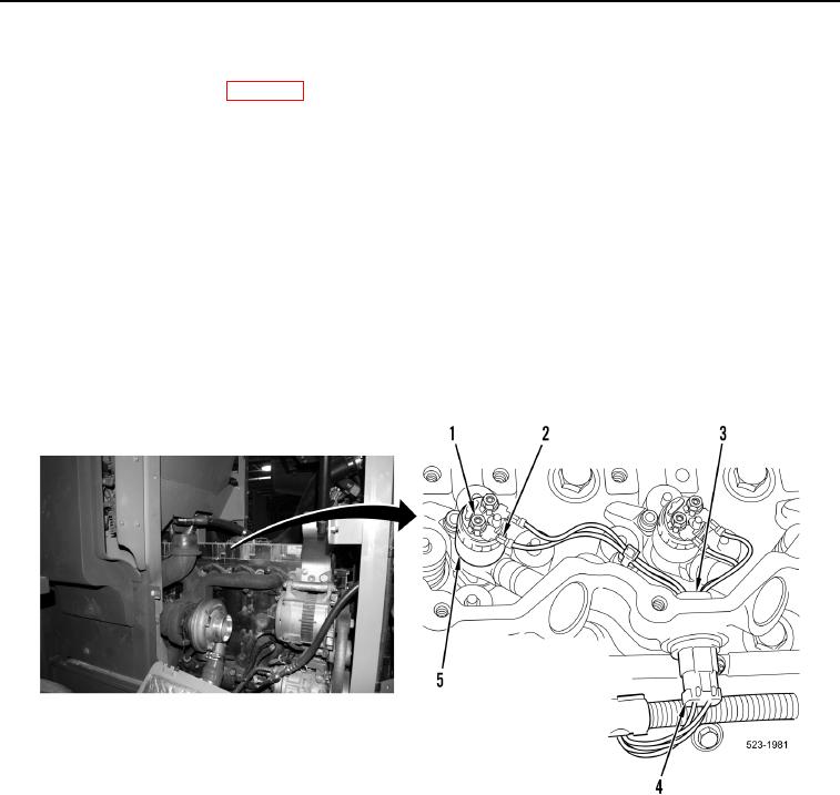
3. Remove 12 nuts (Figure 4, Item 1) and disconnect 12 injector jumper harness terminals (Figure 4, Item 2) from
six fuel injectors (Figure 4, Item 5).
NOTE
Tag and mark connectors aid installation.
4. Disconnect three engine wiring harness connectors (Figure 4, Item 4) from three injector jumper harness
connectors (Figure 4, Item 3).
Figure 4. Fuel Injector Harness.
0187
NOTE
Do not remove bolts from valve cover base.
Loosen bolts in sequence to prevent distortion of valve cover base.