
TM 5-3805-298-23-2
0187
VALVE COVER BASE INSTALLATION CONTINUED
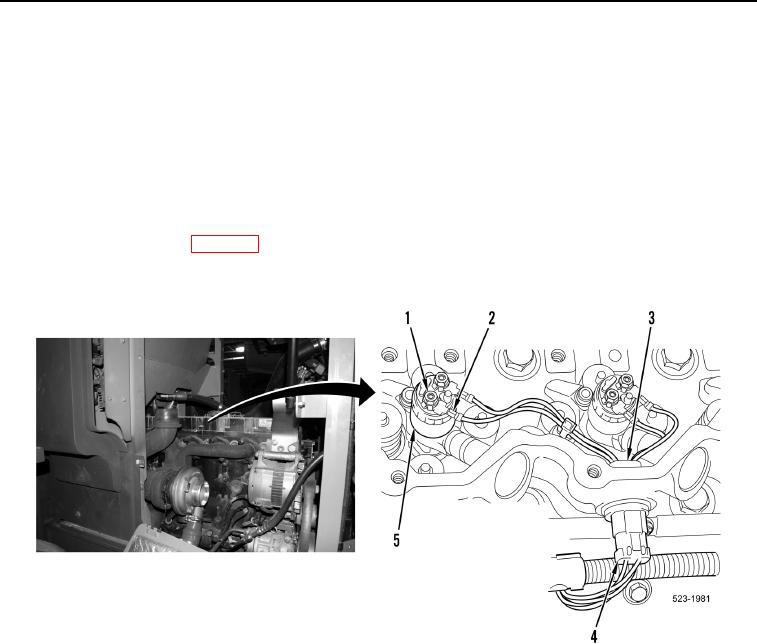
4. Connect three engine wiring harness connectors (Figure 6, Item 4) on three injector jumper harness
connectors (Figure 6, Item 3).
NOTE
Install connectors as noted during removal.
Route and install wires and wiring harnesses as noted during removal.
5. Connect 12 injector jumper harness terminals (Figure 6, Item 2) and nuts (Figure 6, Item 1) on six fuel injectors
(Figure 6, Item 5).
6. Install primary fuel lines (WP 0210).
7. Install valve cover (see procedure in this work package).
Figure 6. Fuel Injector Harness.
0187
END OF TASK