
TM 5-3805-298-23-2
0187
VALVE COVER INSTALLATION CONTINUED
NOTE
Ensure wires and wiring harnesses are not in contact with rocker arms or pinched by valve
cover.
Install bolts as noted during removal.
Tighten bolts in sequence shown.
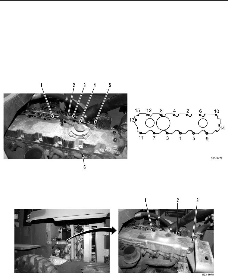
2. Install valve cover (Figure 8, Item 1) and 15 bolts (Figure 8, Item 5) on valve cover base (Figure 8, Item 6).
Tighten bolts in sequence shown (Figure 8) to 79 lb-in (9 Nm).
3. Install breather hose (Figure 8, Item 2) and clamp (Figure 8, Item 3) on breather (Figure 8, Item 4).
Figure 8. Valve Cover.
0187
4. Install heat shield (Figure 9, Item 2) and five bolts (Figure 9, Item 1) on valve cover (Figure 9, Item 3).
Figure 9. Heat Shield.
0187
END OF TASK