
TM 5-3805-298-23-2
0203
REMOVAL CONTINUED
NOTE
Fuel injection pump must remain locked until procedure instructs to unlock.
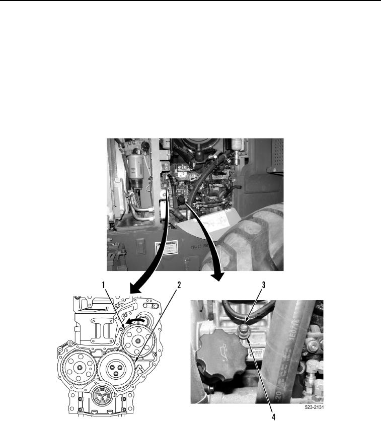
9. Apply pressure to fuel injection pump gear (Figure 4, Item 1) in a counterclockwise direction.
10. Mark position of three gears (Figure 4, Item 2) in order to show alignment during installation.
11. Loosen lock bolt (Figure 4, Item 3) and slide locking washer (Figure 4, Item 4) to big hole allowing lock bolt to
fully engage.
12. Tighten lock bolt (Figure 4, Item 3) to 80 lb-in. (9 Nm).
Figure 4. Fuel Injection Pump Lock.
0203