
TM 5-3805-298-23-2
0203
REMOVAL CONTINUED
NOTE
Steps 1316 describe assembly of tool,
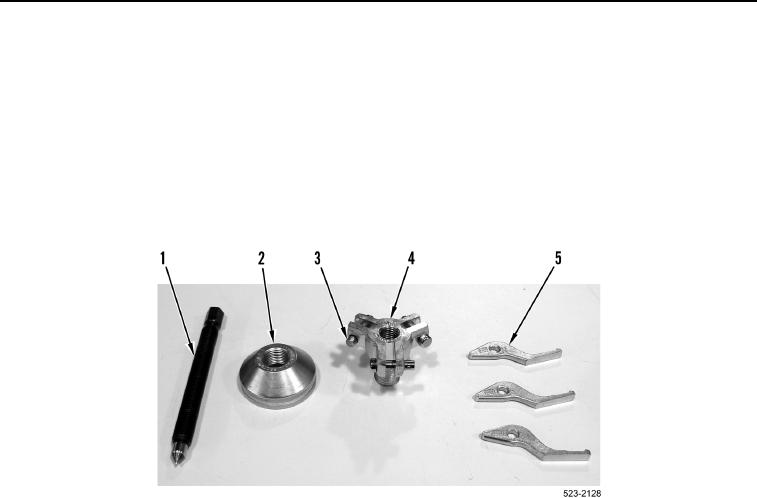
13. Install shaft 4205S (Figure 5, Item 1) into puller body 4255-B (Figure 5, Item 4).
14. Remove three pins (Figure 5, Item 3) from puller body 4255-B (Figure 5, Item 4).
15. Install three jaws 4056-2 (Figure 5, Item 5) and pins (Figure 5, Item 3) on puller body 4255-B (Figure 5, Item 4).
16. Install cone 4250N (Figure 5, Item 2) on puller body 4255-B (Figure 5, Item 4).
Figure 5. Puller Assembly.
0203