
TM 5-3805-298-23-2
0203
REMOVAL CONTINUED
NOTE
Note position and location of tiedown straps to aid installation.
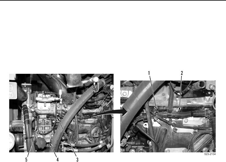
27. Remove tiedown straps (Figure 10, Item 1) from engine control wiring harness (Figure 10, Item 2). Position
engine control wiring harness aside.
28. Disconnect tube (Figure 10, Item 5) from fuel injection pump (Figure 10, Item 4).
29. Remove tube (Figure 10, Item 5) from clips (Figure 10, Item 3). Position tube aside.
Figure 10. Engine Control Wiring Harness.
0203