
TM 5-3805-298-23-2
0203
REMOVAL CONTINUED
NOTE
Tag and mark wiring harness connectors and note wiring harness routing to aid
installation.
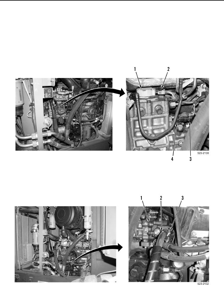
22. Disconnect engine control wiring harness connector (Figure 7, Item 2) from fuel pump solenoid
(Figure 7, Item 1).
23. Disconnect engine control wiring harness connector (Figure 7, Item 3) from camshaft speed sensor
(Figure 7, Item 4).
Figure 7. Engine Control Wiring Harness Connectors.
0203
24. Loosen clamp (Figure 8, Item 3) and remove fuel supply hose (Figure 8, Item 2) from fuel injection pump
(Figure 8, Item 1).
Figure 8. Fuel Supply Hose.
0203