
TM 5-3805-298-23-4
0370
REMOVAL CONTINUED
NOTE
Note position and orientation of fittings for installation purposes.
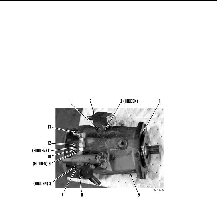
8. Loosen jam nut (Figure 6, Item 1) and remove tee fitting (Figure 6, Item 2) and O-ring (Figure 6, Item 3) from
implement pump (Figure 6, Item 5). Discard O-ring.
9. Loosen jam nut (Figure 6, Item 7) and remove fitting (Figure 6, Item 6) and O-ring (Figure 6, Item 8) from imple-
ment pump (Figure 6, Item 5). Discard O-ring.
10. Loosen jam nut (Figure 6, Item 12) and remove elbow fitting (Figure 6, Item 13) and O-ring (Figure 6, Item 11)
from fitting (Figure 6, Item 10). Discard O-ring.
11. Remove fitting (Figure 6, Item 10) and O-ring (Figure 6, Item 9) from implement pump (Figure 6, Item 5). Dis-
card O-ring.
12. Remove O-ring (Figure 6, Item 4) from implement pump (Figure 6, Item 5). Discard O-ring.
Figure 6. Implement Pump Fittings.
0370
END OF TASK
CLEANING AND INSPECTION
000370
Clean and inspect all components IAW Mechanical General Maintenance Instructions (WP 0172).
END OF TASK