
TM 5-3805-298-23-4
0370
INSTALLATION
000370
CAUTION
Remove all hydraulic opening and component connection caps as installed during
removal. Failure to follow this caution may result in damage to equipment.
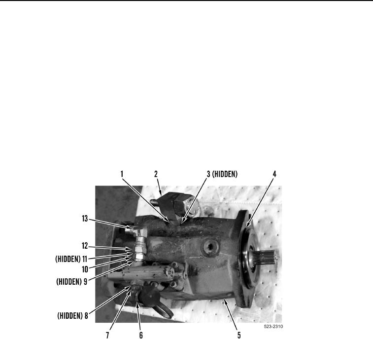
1. Install new O-ring (Figure 7, Item 4) on implement pump (Figure 7, Item 5).
2. Install new O-ring (Figure 7, Item 9) and fitting (Figure 7, Item 10) on implement pump (Figure 7, Item 5).
3. Install new O-ring (Figure 7, Item 11), elbow fitting (Figure 7, Item 13) and tighten jam nut (Figure 7, Item 12)
on fitting (Figure 7, Item 10).
4. Install new O-ring (Figure 7, Item 8), fitting (Figure 7, Item 6) and tighten jam nut (Figure 7, Item 7) on imple-
ment pump (Figure 7, Item 5).
5. Install new O-ring (Figure 7, Item 3), tee fitting (Figure 7, Item 2) and tighten jam nut (Figure 7, Item 1) on
implement pump (Figure 7, Item 5).
Figure 7. Implement Pump Fittings.
0370