
TM 5-3805-298-23-4
0371
REMOVAL CONTINUED
NOTE
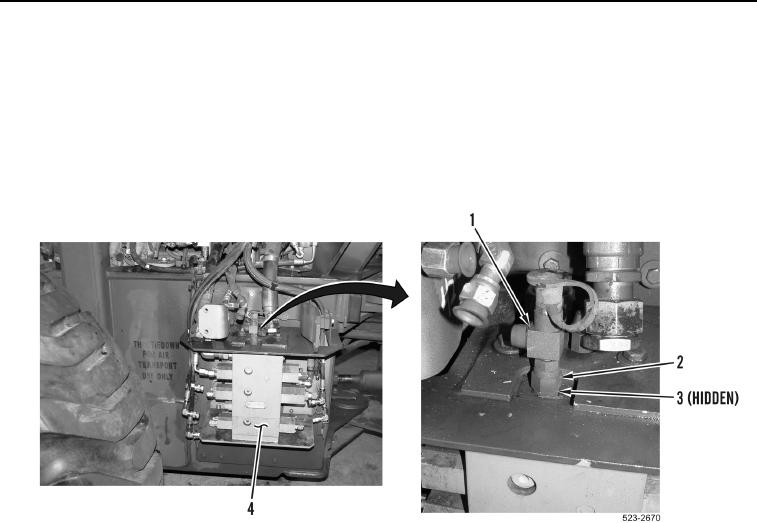
Note position and orientation of fittings to aid installation.
Cap or plug fittings to protect against contamination.
8. Loosen tube nut (Figure 5, Item 2) and remove test port fitting (Figure 5, Item 1) and O-ring (Figure 5, Item 3)
from main control valve (Figure 5, Item 4). Discard O-ring.
Figure 5. Test Port.
0371