
TM 5-3805-298-23-4
0371
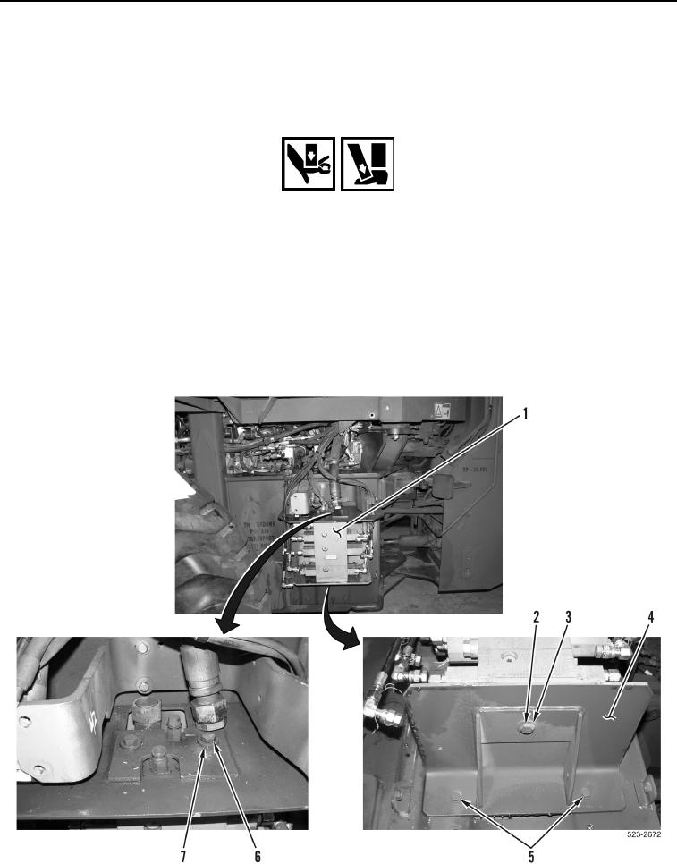
REMOVAL CONTINUED
12. Remove two bolts (Figure 7, Item 6) and washers (Figure 7, Item 7) from main control valve (Figure 7, Item 1).
13. Loosen two bolts (Figure 7, Item 5) approximately 2 1/2 turns from main control valve mounting plate
(Figure 7, Item 4).
WARNING
Use extreme caution when handling heavy parts. Provide adequate support during
procedure. Ensure any lifting device used is in good condition and of suitable load
capacity. Keep clear of heavy parts supported only by lifting device. Failure to follow this
warning may result in injury or death to personnel.
NOTE
Main control valve weighs approximately 99 lb (45 kg).
14. With assistance remove bolt (Figure 7, Item 2), washer (Figure 7, Item 3), and main control valve (Figure 7,
Item 1) from machine.
Figure 7. Mounts.
0371